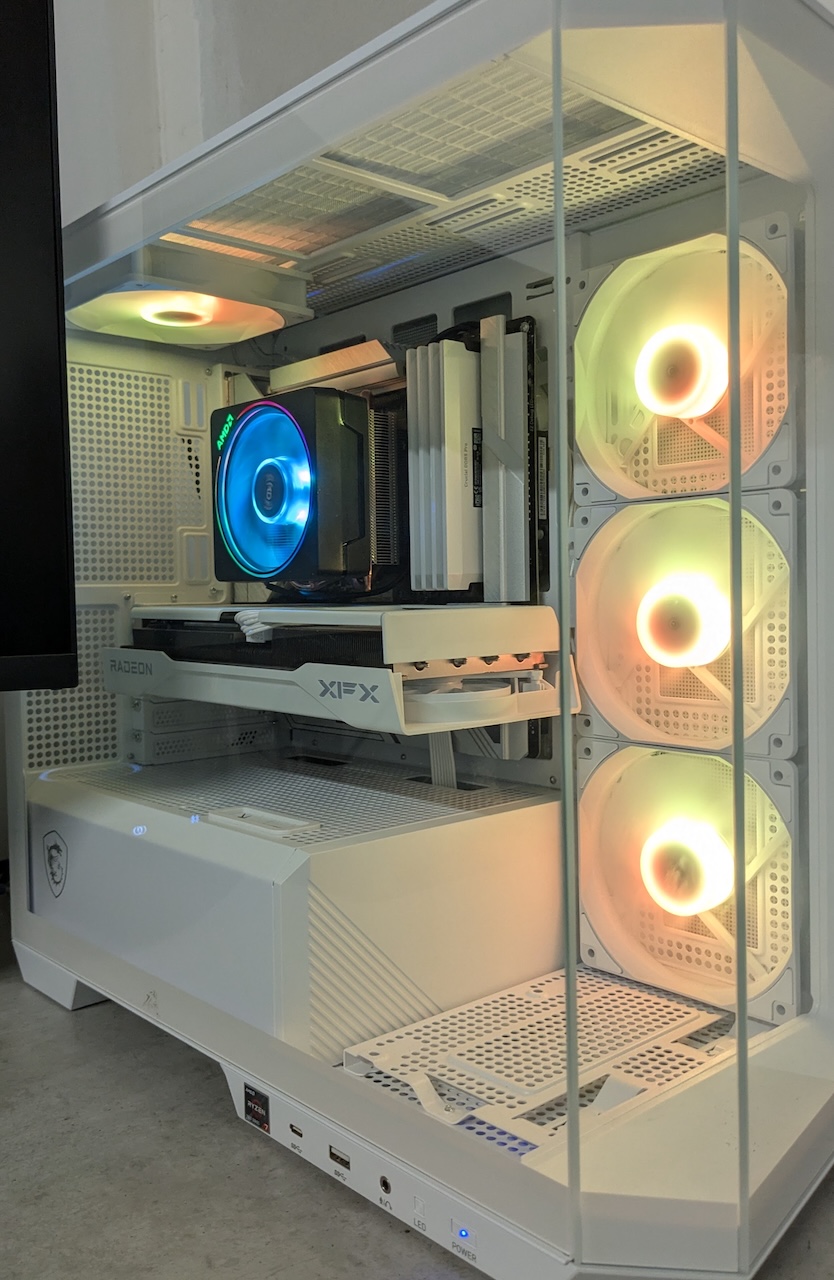
The finished build showcasing the Project Zero aesthetic
Project Zero Assembly Link to heading
10 June 2025 brought the final component; the XFX 9060 XT Swift 16GB graphics card. After six months of strategic part purchasing, final assembly day had finally arrived. The Project Zero build concept promised zero visible cables, but delivering on that promise required some unconventional assembly techniques and a few creative workarounds.
This is the detailed assembly guide I wished I’d had when starting this build. Project Zero systems require a different approach than traditional builds, and some components needed modification to achieve the cable-free aesthetic. While I’m writing this from the perspective of a complete build, I didn’t get the GPU until the very end but it doesn’t change the order of operations.
Safety First: Protecting the Glass Link to heading
Before touching any components, the tempered glass side panel goes onto a towel or blanket immediately. This isn’t paranoia; tempered glass panels are notorious for exploding when they contact hard surfaces. The thermal stress from temperature changes combined with any surface imperfection can cause spontaneous shattering.
A thick towel on carpet provides the safest resting place. The glass stays there until the very final step of assembly. No exceptions.
Step 1: Power Supply Foundation Link to heading
The PSU goes in first with only the cables you actually need. Modular power supplies are essential for clean builds, but the Project Zero concept takes this further; every unused cable is visual clutter, even if hidden behind the motherboard.
For this build, that meant:
- 24-pin motherboard power
- Two 8-pin CPU power cables
- One 8-pin PCIe power cable for the GPU
- SATA power for the case fan controller
The ThermalTake 850W Gold+ came with a selection of chunky white ribbon cables that complement the all-white theme. Cable selection at this stage saves significant routing headaches later.
Step 2: Motherboard Installation - The Project Zero Challenge Link to heading

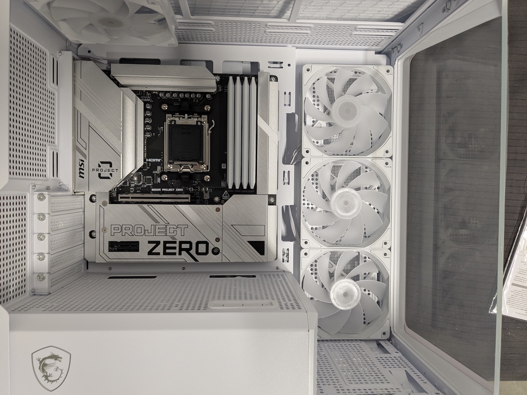
The MSI B650M Project Zero motherboard installed
Here’s where Project Zero builds differ dramatically from traditional assembly: the CPU and other components cannot be properly seated with the motherboard outside the case. The rear I/O connectors that make Project Zero possible are fragile in some cases and protrude at various positions around the back of the board. Pressure can only be applied to the component slots when the motherboard is fully installed on the case tray.
This means:
- No dry-fitting components on a workbench
- All connections must be planned in advance
- The motherboard goes straight into the case with no testing
The MSI B650M Project Zero mATX board aligns on the case mounting standoffs very well, but you cannot apply pressure to seat connectors until it’s fully secured. This reverses the normal build order and requires more confidence in component compatibility.
Step 3: CPU and Memory - The Pressure Game Link to heading
With the motherboard secured in the case, the CPU and RAM installation becomes the next critical step. Both components require more installation force than most builders are comfortable applying, but proper seating is essential.
CPU Installation Link to heading
The CPU installation requires considerable force to close the lever
The Ryzen 7 7700 has a gold corner marker that aligns with the socket’s corresponding indicator. Lower the retention arm, place the CPU (it should drop in with zero resistance), fold the retainer over the CPU and then close the retention arm. The pressure required feels excessive, but AMD sockets are designed for this force. If the retainer doesn’t close easily and meet the securing lever, the CPU is likely misaligned; remove and try again.
Memory Installation Link to heading
64GB (4 x 16GB) Crucial DDR5 in match pairs
DDR5 modules come in matched pairs and are installed in dual-channel configuration for optimal performance. Before mixing them up, take a sharpie and make a small dot on the edge of each module to identify pairs. You will appreciate this later if and when troubleshooting.
The slots have an offset tooth that prevents incorrect insertion too. Each module requires firm, even pressure until you hear the retention clips snap into place. Note though that the slots on this particular model only have clips on one side–the side nearest the edge.
64GB across four slots meant repeating this process four times, with each module requiring the same confident pressure. The satisfying click when properly seated is unmistakable; you’ll know when it’s right.
Step 4: NVMe Storage - Keep It Simple Link to heading

4TB Corsair P3+ and 256GB boot NVMe installed
The 4TB SSD installation was refreshingly straightforward after the pressure-sensitive CPU and RAM. The process is as follows:
- Remove the motherboard’s M.2 heat spreader
- Install the standoff at the 2280 position (standard for most consumer NVMe drives)
- Insert the SSD at a 30-degree angle, taking care to align the notch, and fully seat it in the connector
- Press down until it sits flat against the standoff
- Secure with the retention screw
- Replace the heat spreader
Unlike CPU and RAM, NVMe installation should feel effortless. If there’s resistance, stop and check alignment; forcing an NVMe drive can damage both the drive and motherboard.
Step 5: Graphics Card Modification Link to heading

The XFX Radeon 9060XT 16GB with a mostly hidden power cable
This was the most challenging part of the entire build. The XFX 9060 XT Swift doesn’t hide power cables like higher-end cards (the Sapphire NITRO+ 9070 XT routes cables beautifully to the bottom edge). The Sapphire NITRO 9060 XT design shows clear evidence that hidden cable routing was intended, but not implemented in the final product. Being $130 more than the XFX, I wasn’t ready to spend the extra if I wasn’t getting this premium feature.
Without budget for a $1,700 graphics card, modification was necessary. The XFX shroud design made this possible:
- Remove four screws at the back of the shroud, furthest from the PCB
- Carefully lift the rear portion to access the PCIe power connector area
- Route the 8-pin power cable under the shroud, and connect it to the GPU
- Position the cable to minimise visibility from the front
- Reassemble the shroud with cable hidden
The modification took patience and careful planning but it’s not impacting any sensitive areas of the GPU, and the result justifies the effort. From the front, the graphics card power source is barely noticeable; exactly the Project Zero aesthetic I wanted.
Align the card with the PCIe slot and gently but firmly press down until it clicks into place. Secure with two screws (or possibly three depending on your card) to the case bracket.
Step 6: CPU Cooler - Last But Largest Link to heading
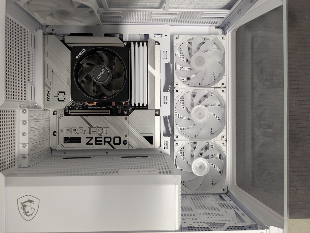
The AMD Wraith Prism CPU cooler installed
The Wraith Prism cooler that comes with the Ryzen 7700 goes in last for good reason; it’s the largest cooling component and would get in the way of everything else if installed earlier. There is no white version but the black shroud and fan cable sleeves blend in with the motherboard and match the build theme.
Installation is standard AMD: remove the plastic AM5 socket cover, apply the pre-installed thermal paste, and secure with the retention mechanism. The Wraith Prism’s size means careful positioning to avoid interference with RAM and GPU–it’s snug, but not mini-ITX levels of snug that also equate to fiddly.
Update September 2025: The Wraith Prism cooler has been discontinued by AMD and no longer ships with the boxed Ryzen 7 7700. For future builds, consider an AIO liquid cooler or a high-quality air cooler in white to maintain the aesthetic.
Step 7: Cable Management - The Mullet Problem Link to heading
Project Zero builds have a “mullet” problem: business up front, party out the back. The visible side is clean and cable-free, but the reverse side becomes a cable management nightmare.
The key is systematic organisation:
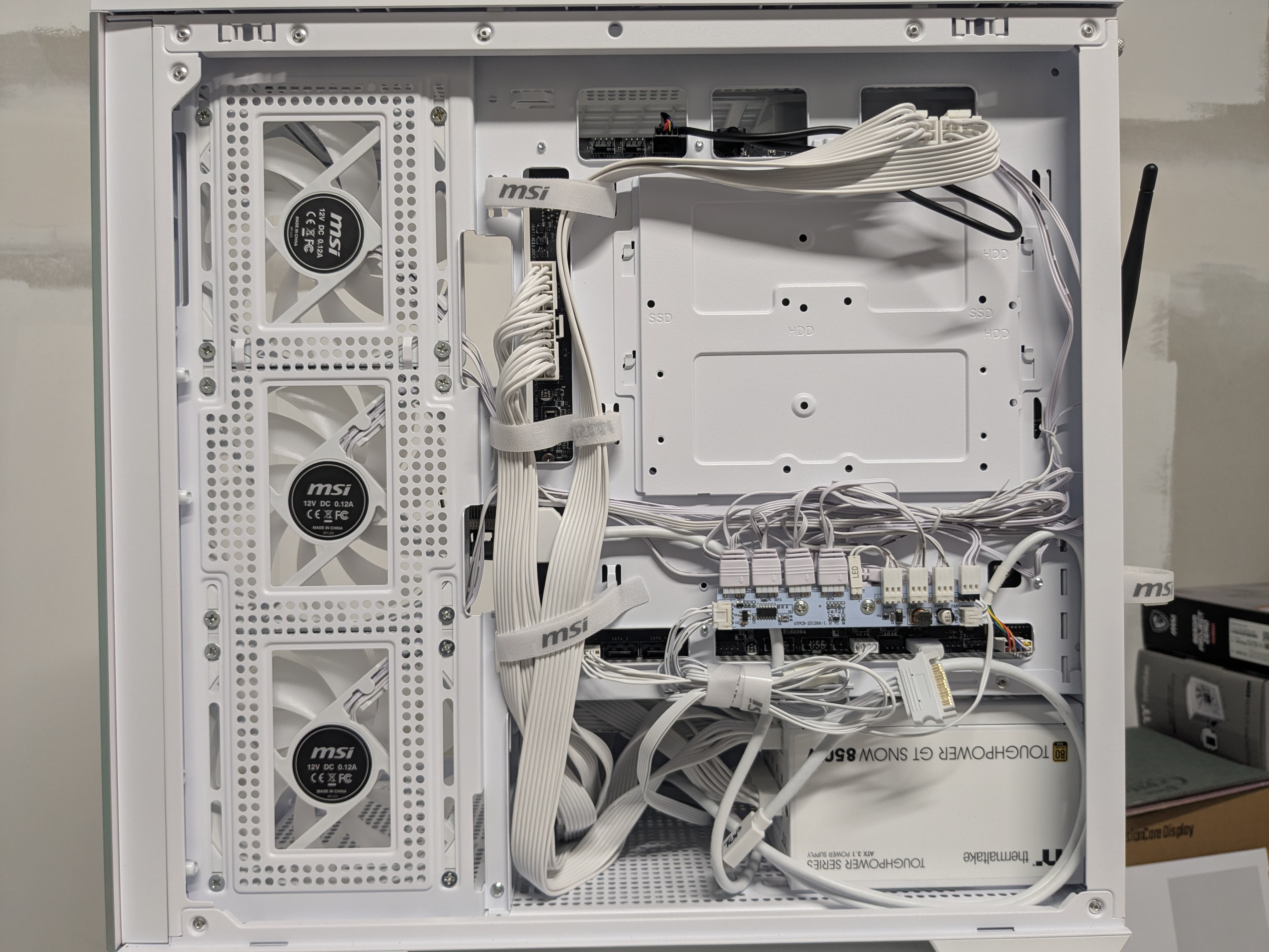
The 'mullet' of cables at the back of the case
Power Cables (Thickest) Link to heading
Route these first as they take the most space and are the least flexible. The 24-pin motherboard and 8-pin CPU cables are the bulkiest and determine routing paths for everything else.
Signal/Data Cables Link to heading
Front panel, audio and USB headers are next. These are smaller than power cables but more rigid than fan cables. Group them together and route as required, noting the socket locations on the motherboard.
Peripheral Cables (Thinnest But Most Numerous) Link to heading
Fan headers, RGB connections, and case lighting create the most complexity. The MSI Mag Pano comes with an impressive number of fans and lighting zones, meaning a dozen or more thin cables that must be individually routed.
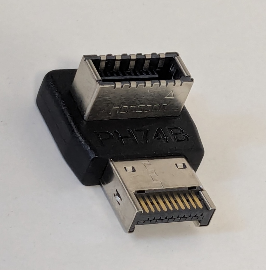
The Type-H USB 3 plug needs this right-angle adapter
The MSI-Specific Challenge Link to heading
The case includes a fan and lighting controller that requires a 2.5" SATA power connection; easy to forget but essential for proper operation. More frustrating is the USB-C front panel connector that uses a straight connector where the case design demands a right-angle connection.
MSI never addressed this design flaw, so you’ll need a USB-C PH74B right-angle adapter from Amazon or eBay (around $7-10). It’s a cheap fix for a premium case’s design oversight.
Step 8: Final Assembly and First Boot Link to heading
With cable management complete, the back panel snaps on without pressing against cables; the sign of proper routing. MSI provides generous velcro straps and routing points that make this achievable even with the cable density of a Project Zero build.
Final checks with the case upright:
- All components properly seated
- No loose connections
- Cable routing clear of fans
- Glass panel ready for installation
Connect your keyboard, mouse, video output, and power, then press the power button for the first time. A successful POST brings you to the BIOS configuration screen; proof that six months of planning and careful assembly have paid off.
The Project Zero Result Link to heading
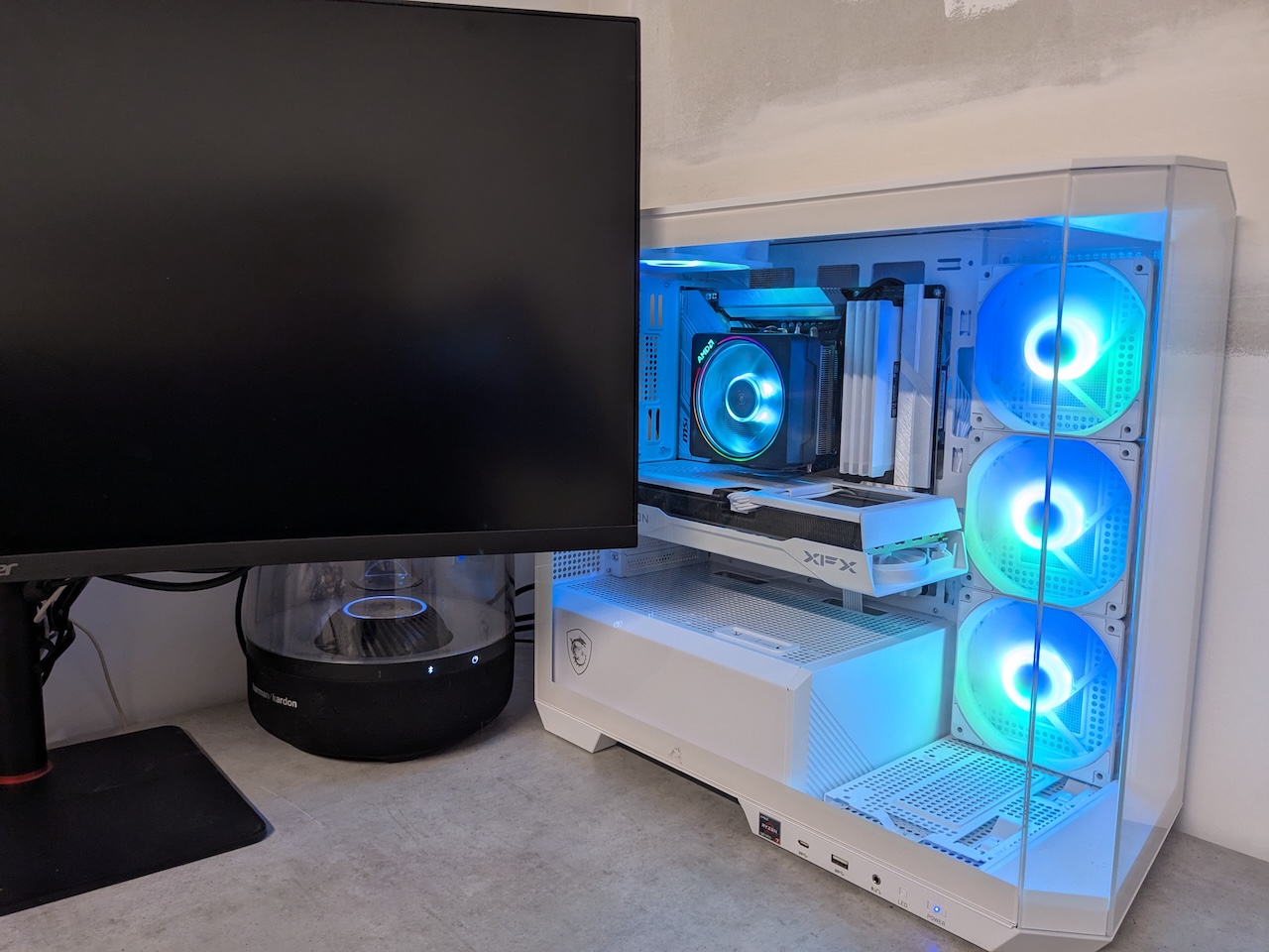
The completed PC setup and running on the desk
The completed build delivers on every promise: zero visible cables, all-white aesthetic, and performance that should last at least five and as many as eight years. The extra effort required for Project Zero assembly creates a result that traditional builds simply cannot match.
The cable management complexity is real, but the systematic approach makes it manageable. The GPU modification was necessary for this budget, but higher-end cards would eliminate that requirement.
Most importantly, the build process itself was satisfying. Every component required thoughtful planning and careful execution. The result isn’t just a functional PC; it’s a demonstration that patience and attention to detail can achieve something genuinely special.
Next up: operating system installation, performance testing, and the final verdict on whether this build concept actually works in practice.
Have you tackled any Project Zero or cable-free builds? What modifications did you need to achieve the aesthetic you wanted?